|
FRAME2Dexpress
is a program for static and dynamic analysis of 2-dimensional framed structures.
Distributed or nodal dead and live loads can be specified. Load combination is used
according to Eurocode 1, with user defined load combination coefficients. The program
performs computation of internal forces and diagrams for displacements,
bending moments, shear and axial forces. In the dynamic analysis the eigenfrequencies and
the mode shapes are computed. Graphical output for the diagrams and mode shapes is
displayed.
For educational purposes FREE Lite version.(
Structure wizard and steel profiles not included in Lite version)
New upgraded version
FRAME2Dexpress + EC Design |
The program has been designed to be easy and fast in use.
- The structure is defined by structure
prototype wizard, with 21 ready types of frames or by giving the nodal coordinates and the
element connectivity.
- The graph of the structure appears
simultaneously with the data you enter.
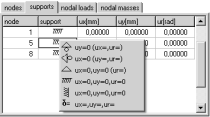
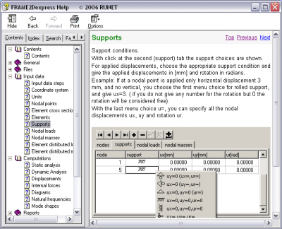
- The support conditions are defined from
graphical menu.
- The cross sections are defined either with the area and inertia properties, or by their
dimensions ( rectangular, T or L type sections).
- For steel structures, lists of every nominal steel profile available with its
properties.
- Nodal loads have dead and live components.
- Element distributed loads (uniform,
triangular, parabolic), with dead and live components. The self weight may or may not be
included. Element distributed load direction, vertical, horizontal or perpendicular to the
elements.
- The load combination coefficients may be
defined by the user.
- Material properties can be picked from menu.
- Nodal masses corresponding to dead or live
loading.
- Mass combination coefficients for nodal masses or element distributed masses due to dead
and live weight may be defined by the user.
- In reports, the values of deformations are included
in addition to bending moments, shear force and axial force in the diagrams of every
element.
- Units : Metric units.
|
|
|
Frame prototypes for easy generation of structural models
 |
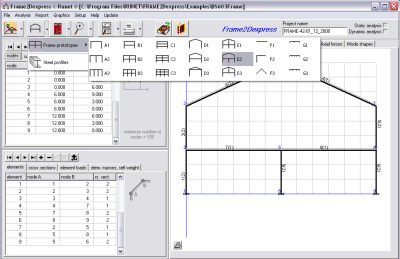 |
New structure
prototype wizard, with 21 ready types of frames.
The nodal points are defined through
their x,y coordinates
For every element with unique numbering the
end nodal points and the cross section number are defined. The cross section number must
be defined in the element cross section data.
|
|
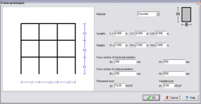 |
After choosing the type of structure it is easy to adjust the structure's
materials and dimensions.
Materials: Concrete, Steel or timber
|
|
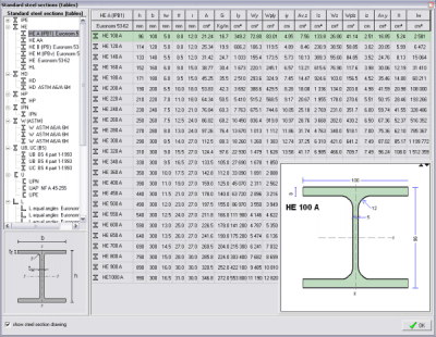 |
- For steel structures, lists of every nominal
steel profile available with its properties.
|
| 
 |
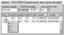
The user can select structural material (e.g.
general, concrete, steel, timber). The cross section can be defined by the area and moment
of inertia, or by the dimensions b,h for orthogonal cross sections or by the dimensions
b,b1,h,h1 for T type sections. The user can select the cross section units.
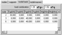
Nodal loads
are easily defined for the corresponding nodes, from a graphical menu. |
 |
Nodal forces are in the x, y direction in
[kN], and nodal moments in kNm. The loads have dead and live components. The loading in
the static analysis is taken as CgxFg+CqxFq, where Cg and Cq are the load combination
coefficients. Default values are Cg=1.35 and Cq=1.50 (Eurocode 1, EC1).
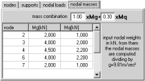
Lamped nodal masses, corresponding to
dead or live loading.
The mass in the dynamic analysis are taken as CgxFg+CqxFq. Default values are Cg=1.00 and
Cq=0.30 (Eurocode 1, EC1).
|
 |
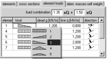
- Element distributed loads
Element distributed loads, dead and live in
kN/m. You can select among five different types of distributed loads from a menu. The kind
of the distributed loads are: uniformly distributed, triangular with maximum value at the
right or the left element end, symmetric triangular, and symmetric parabolic. You can also
select the loading direction, perpendicular to element axis, vertical or horizontal, from
a menu.
The loading in the static analysis is taken as CgxFg+CqxFq, where Cg and Cq are the load
combination coefficients. Default values are Cg=1.35 and Cq=1.50 (Eurocode 1, EC1).
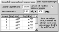
- Element distributed masses
Distributed
masses in structure elements corresponding to dead or live loading. The mass in the dynamic analysis are taken as
CgxFg+CqxFq. Default values are Cg=1.00 and Cq=0.30 (Eurocode 1, EC1). You can select
to include the self-weight or not in the masses. |
| Static and dynamic analysis of a model |
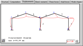 |
 Results of
static analysis: Results of
static analysis:
- Nodal displacements
- Displacements along each elements.
- Internal forces at element ends in global
and local coordinate system.
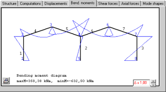
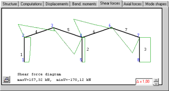
- Internal forces (bending moments, shear and
axial forces) along each element.
- Diagrams of displacements.
- Diagrams of deformations, bending
moments, shear forces and axial forces.
|
|
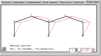 |
 Results of dynamic
analysis: Results of dynamic
analysis:
- Natural frequencies
- Diagrams of mode shapes
|
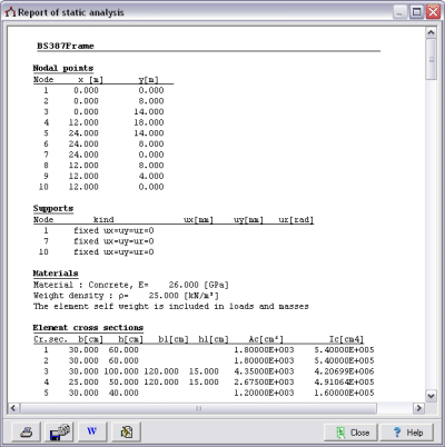 |
 Preview PreviewYou can view, print, save to file and send to
Word the reports.
printout of static analysis:
- Nodal displacements
- Displacements along each
elements.
- Internal forces at element ends
in global and local coordinate system.
- Internal forces (bending
moments, shear and axial forces) along each element.
- Diagrams of displacements.
- Diagrams of bending moments,
shear forces and axial forces.
printout of dynamic analysis:
- Natural frequencies
- Diagrams of mode shapes
Additional
printouts
- Stiffness and mass matrices.
- Equilibrium equations
- Eigenvalue equations
|
|
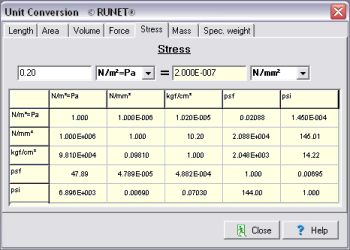
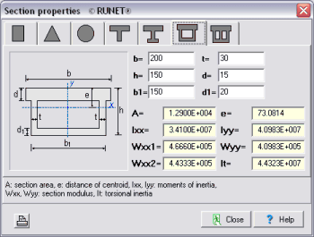
 Engineering tools Engineering tools
- Unit conversion
- Area calculations
- Section of properties (areas, mometns of
inertia)
- Calculation Rolled steel shapes
|
|
Revised:
november 01, 2022 |
 On line help On line helpA context-sensitive Help system, guides you through the use of the program.
On-line user's manual and frequently asked
questions (F.A.Q.) are included in the program.
User's manual included.
You can preview, or print the program
user's manual. You can select to view it as a Word (doc) or as an Acrobat (pdf) document. |
 |
|
|