New features in BETONexpress
05/2015:
·
Flat slab, Punching shear
·
Flat slab design
·
Foundation Bearing resistance
·
Fundaments of Steel columns
·
Water basins
·
Basement walls
·
Bearing walls
·
Walls with horizontal distributed load |
 |
|
|
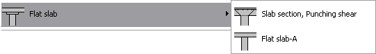
Flat slab, Punching shear |
 |
|
Design of slab section in punching shear
according to Eurocode 2 § 6.4. Verification of the shear capacity at
the control perimeters around a rectangular column. If the design
shear vEd exceeds the shear capacity vRd,c the program computes the
necessary shear (links) reinforcement. |
 |
|
|
Flat slab design |
|
Design of flat slab with inner span
dimensions Lx, Ly and outer span dimensions Lx’ and Ly’.
Specify
Yes or
No if you want to use shear
reinforcement.
If Yes, then the appropriate shear
reinforcement will be computed if the shear force βVEd>VEd,c.
If No is checked for shear reinforcement,
the punching shear is checked so βVEd>VRd,c.
If design
is not verified, a message to increase the slab thickness is shown.
|
 |
|
The bending moments of the flat slab panels are apportioned in
column and middle strip according to Eurocode 2 Annex I as follows:
·
Negative moments: column strip 70%, middle strip 30%
·
Positive moments :
column
strip 55%, middle strip 45%
The column strip in both x and y direction
is equal to min (Lx,Ly)/2.
|
|
|
Foundation Bearing resistance |
 |
|
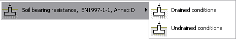
The basis for the design of foundations is the bearing resistance of
the soil.
The design bearing resistance can be calculated using
analytical or semi-empirical methods. Annex D of Eurocode 7,
EN1997:2004 describes a method of obtaining the design bearing
strength of the soil.
|
|
The methods of Annex D Eurocode 7, EN1997:2004 for drained and
undrained conditions are implemented in the program.
The design
bearing strength of the soil is estimated for EQU, STR and GEO
conditions.
The computation of design bearing strength is for
drained and undrained soil conditions.
For drained soil conditions the important soil property is the angle
of shearing resistance φk [°] and the cohesion intercept
c[kPA].
For undrained soil conditions the important soil
property is the undrained strength cu [kPa].
For the
computation of design bearing strength other parameters are the
dimensions and depth of the footing, as well as the loading and the
load eccentricities.
In all the designs of footings and retaining walls the
 utility has been
added. utility has been
added.
Click the button and the design of fundaments or in the
design of retaining walls and you get into a calculation window for
design bearing resistance.
|
 |
|
|
|
 |
|
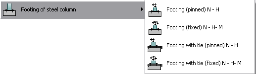
The concrete footing of steel structures has to be designed to
resist soil pressure for maximum vertical load and it must have
enough weight to resist uplift (from wind or seismic forces).
You can design Pin
and Fixed end
column foundations.
You can also specify if the foundation has a horizontal tie to take
the horizontal outwards forces or not.
|
Loading on the fundament
The final actions after multiplication with safety factors (γG
and γQ) Eurocode-1990-1-1, Table A1.2
For downwards loading usual values are:
γG =1.35
(unfavourable), γQ=1.50.
For
upwards (uplift) loading usual values are:
γG =0.90
(favourable), γQ=0.00.
|
 |
|
Steel Tie and Passive earth
pressure
The high horizontal forces acting at the
base are acting outwards as a result of bending in the columns due
to vertical loading on the roof. This is resisted in two ways.
|
|
·
Steel tie at column base
A tie cast into the floor slab connected to the base of the columns.
This should be considered more safe method to resist the horizontal
forces at the base of the columns.
|
 |
|
·
Passive
earth pressure on the side of the foundation
In this case the earth filling and compacting on the side of the
foundation must be performed carefully, so that the passive earth
pressure is not reduced. The fundament transverse width By and the
height Bh are used to compute the active area for passive earth
pressure. |
 |

If you pressed the predimensioning, the foundation dimensions (if
not checked) are adjusted by the program so the fundament weight is
enough to resist uplift forces. The width By and the height are also
for adequate passive earth force to resist the horizontal base force
outwards.
|
|
|
Water basins, swimming pools |
|
Design of rectangular water basins.
The solution is for a 2-dimensional cross section across the
smallest dimension (width) of the basin.
The basic dimensions
are the width of the basin B [m], the length of the basin L [m] and
the depth of the basin H [m].
The basin is assumed to sit on elastic
ground and is analyzed with finite element analysis. The basin walls
are subdivided in 2 beam elements of length H/2.
The basin
floor is modelled with 16 beam elements with nodal points connected
to the ground with elastic springs. The
stiffness of the elastic springs is computed from the Winkler’s
foundation modulus Ks [kN/m2/m].
The loading conditions include all the load cases according to
Eurocode 0 (EQU, STR and GEO) for:
· Empty water basin (only earth pressure)
· Filled water basin without earth pressure
· Filled water basin with earth pressure
The reinforced concrete
design includes also serviceability control with limit crack width
specified by the user.
|
 |
|
|
Basement walls |
|
 |
|
There are two kinds of basement walls:
·
Walls with only the bottom restrained for lateral movement.
·
Walls with restrained the bottom and the top for lateral movement.
In the first case the sliding of the wall is prevented due to
the retraining of the base in movement. The active earth pressure is
computed as usual using Coulomb’s (1776) or Rankine’s (1857) theory,
Eurocode 7 § 9.5.1.
In the second case (when the wall top is also prevented from lateral
movement) the active earth pressure conditions are obtained for Ko
in rest conditions according to Jaky (1948), Eurocode 7 § 9.5.2.
|
|
|
Bearing walls |
 |
|
Bearing walls in vertical or horizontal load on the top without any
earth pressure.
The horizontal load on the top can be defined
from Eurocode 1-1-1:2001 Table 6.12 according to National Annexes.
The horizontal load on the top can be also defined according to
Eurocode 1-1-7:2006, in case of impact load.
|
|
In case of wind loading the wind pressure is according to Eurocode
1-1-4:2005. |
 |
|
|
|